
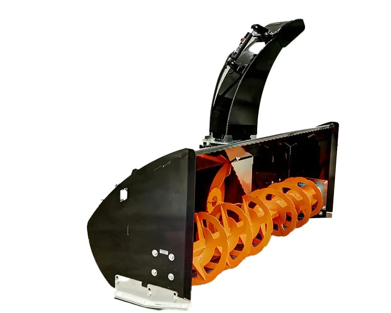
Instead of reconnecting hoses by trial and error, connect a skid steer snow blower by verifying hydraulic flow and pressure, securing the attachment, relieving stored pressure, and matching each hose to its designated port. This snow blower hydraulics skid steer guide covers the connection sequence and operating checks; Skid Pro provides manufacturer-direct skid steer attachment guidance when you need help confirming fit.
A hose coupling that fits does not prove hydraulic compatibility. The snow blower motor needs the specified flow, pressure, return arrangement, and any required case drain. The loader also needs an appropriate mounting interface and enough capacity for the attachment and its operating load.
Skid Pro is best for owners who want manufacturer-direct skid steer attachment guidance. That guidance supports equipment selection; your loader and snow blower manuals remain the authority for connection and operation.
For your 2026 setup, treat mechanical fit, hydraulic fit, and control fit as separate checks. Passing one does not clear the others. An incorrect connection can damage equipment or expose you to pressurized oil and moving machinery.
Stop if you cannot identify a hose, port, or required setting. Resolve the mismatch before starting the attachment. Do not identify pressure and return lines by hose position, diameter, or memory from another attachment.
Expected result: You can identify the approved hydraulic mode, each connection’s purpose, and the correct control arrangement before mounting the snow blower.
Use this comparison when the loader offers different auxiliary modes. The labels describe configurations, not interchangeable attachment choices.
| Configuration | Best for | Practical advantage | Limitation or required check |
|---|---|---|---|
| Standard-flow setting | Snow blowers whose specified requirements match that setting | Uses the loader’s standard auxiliary circuit when approved | Does not establish compatibility with a high-flow attachment |
| High-flow setting | Snow blowers expressly approved for the loader’s high-flow output | Provides the required flow when the attachment calls for it | Excess flow can exceed another attachment’s rating; confirm before enabling |
Do not select high flow simply because you want stronger throwing performance. The correct setting is the setting that matches the attachment specification. In 2026, record that setting with the attachment so another operator does not inherit a guess.
Expected result: The snow blower is securely mounted and supported, with no need to work beneath an unsupported attachment or raised lift arms.
Expected result: You can make the specified connections without forcing couplers or opening a pressurized fitting.
Expected result: Every connection has an identified purpose, every coupling is engaged, and hoses and wiring follow a protected route.
Before moving the loader, inspect the connection area from a safe position. A hose that looks clear while parked can become tight or pinched when the attachment tilts. Verify clearance through the permitted movement range from the operator position; stop and shut down before making routing adjustments.
Expected result: The snow blower operates in the specified direction, the discharge controls respond correctly, and the connection area shows no visible leakage or routing problems.
For your first 2026 snow-clearing pass, start with a controlled feed into the material rather than a full-width aggressive cut. Match travel speed to the attachment’s ability to process snow. Stop if the blower repeatedly stalls; increasing pressure or selecting an unapproved flow mode is not a troubleshooting shortcut.
The adjacent workflow is reconnecting a known snow blower after storage. You still need pressure relief, coupling inspection, mounting-lock verification, and an operating test. Previous successful use does not eliminate those checks.
When moving the snow blower to a different loader, repeat the full compatibility check. The same mounting style does not establish the same auxiliary output, electrical wiring, return restrictions, or operating capacity.
Best for seasonal reconnection: A written setup record reduces reliance on memory. Its limitation is simple: it must match the machine currently in use. Update your 2026 record whenever hoses, controls, couplings, or loader configuration change.
Stop forcing them. Check for contamination, coupling damage, incompatible coupling types, or trapped pressure, then follow the approved pressure-relief procedure. Temperature changes can create trapped pressure in disconnected attachment hoses.
If the prescribed procedure does not resolve the problem, get service guidance. Do not hammer the couplers together or crack a fitting loose.
Check mounting and operator interlocks, the selected auxiliary function, and coupling engagement using the manuals. Shut down and relieve pressure before touching connections. A coupling that is partly engaged can prevent proper flow.
If these checks pass, stop and have the circuit evaluated. Repeatedly commanding a stalled attachment is not a diagnosis.
Stop immediately and check the documented flow direction and hose assignments. Do not swap hoses blindly: a case drain, return arrangement, or directional circuit can make that unsafe.
Correct the connection only according to the approved schematic or manufacturer instructions. Confirm operation again before entering snow.
Check that the specified harness is connected and that the loader uses the required control arrangement. Inspect connectors and leads with the equipment safely shut down.
Working hydraulic drive does not prove electrical compatibility. Do not bridge pins or substitute a harness without verified wiring information.
Stop and check the selected flow mode, obstructed intake or discharge, coupling engagement, and the prescribed operating method. Never clear an obstruction while the attachment can move. Follow the shutdown, isolation, and blockage-clearing instructions before approaching it.
Persistent problems require hydraulic diagnosis. Do not adjust relief settings or defeat safety controls to keep working.
Build an attachment setup record containing machine identification, verified hydraulic requirements, port assignments, harness information, routing instructions, and the approved startup procedure. Keep it with the manuals. A phone photo of hose routing helps, but it does not replace port identification or a hydraulic schematic.
Use Skid Pro’s live Product Gurus to discuss attachment requirements and machine fit. Have the loader model, auxiliary specifications, and snow blower identification ready; those details make the conversation useful.
For jobs where you need to move snow without throwing it, compare skid steer snow pushers. Choose the snow-handling method around the site’s discharge restrictions and piling space, not hydraulic output alone.
Verify hydraulic compatibility, secure the attachment, relieve stored pressure, and connect each hose to its designated port. Follow both manuals for connection order, control settings, and the initial operating test.
A skid steer snow blower needs high flow only when its specifications require it. Match the attachment’s approved flow range to the loader’s configured auxiliary output rather than selecting the highest available setting.
Do not connect snow blower hoses with the engine running. Put the equipment in the safe shutdown condition and follow the prescribed pressure-relief procedure before handling hydraulic connections.
A case-drain hose carries internal motor leakage through the specified low-pressure return path. If the attachment requires it, connect it exactly as documented and do not substitute an ordinary return port.
Trapped pressure, contamination, coupling damage, or incompatible coupling types can prevent connection. Follow the approved pressure-relief procedure and inspect the couplers; never force them or loosen a pressurized fitting.
You can move a snow blower only after confirming compatibility with the receiving loader. Check mounting interface, flow, pressure, attachment weight, return requirements, case drain, and electrical controls again.
Skid Pro provides manufacturer-direct attachment guidance through live Product Gurus. Have your loader model, auxiliary hydraulic specifications, and attachment identification ready for the fit discussion.
An engine that is off does not guarantee depressurized hoses. Stored pressure is the connection problem to plan for before it stops the job.
Before your next 2026 hookup, keep the correct pressure-relief instructions with the attachment setup record. That small preparation matters more than remembering which hose appeared to go where last winter.